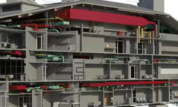
BIM is a creation and digital information management of assets such as buildings, bridges, highways, tunnels, etc.
As the project progresses, the level of detail varies from available information, then a design intent to a virtual construction model, then finally a as-constructed asset information model (AIM).
An employer describes the level of detail in the Employer’s Information Requirements (EIR). The Employers Information Requirements eventually becomes the BIM protocol, which is delivered as a contractual obligation.
The Model and Delivery Table will have the summary of level of detail requirements and model development is responsible for that.
The ‘level of definition‘ is defined by PAS 1192-2 (Specification for information management for the capital/delivery phase of construction projects using building information modelling.) into two components which are not having a vast deviation
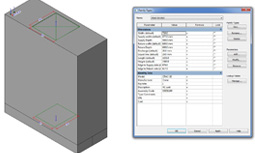
- Levels of model detail (LOD), describes the graphical content of models.
- Levels of model information (LOI), describes the non-graphical content of models.
It allows the owner to verify whether to proceed with the project as the levels of model detail and model information are generally defined in the key stages of the project, at which ‘data drops’ (information exchanges) can be felt. The American Institute of Architects (AIA) has also published a LOD framework for the AIA G202-2013 Building Information Modelling Protocol Form. But the LOD refers to the ‘Level of Development’ required for model element content. In that ‘level of development‘ is used rather than ‘level of detail‘ understanding the reality that a very detailed element which is seen might be generic and else appearances might be at a low level of design development.


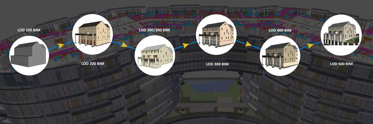
Definition of LOD framework :
- LOD 100: The Model Element may be graphically represented in the Model with a symbol or other generic representation, but does not satisfy the requirements for LOD 200. Information related to the Model Element (i.e., cost per square foot, tonnage, etc.) is taken from other Model Elements.
- LOD 200: The Model Element is graphically represented within the Model as a generic system, object, or assembly with approximate quantities, size, shape, location, and orientation. Non-graphic information may also be there in the Model Element.
- LOD 300: The Model Element is graphically represented within the Model as a specific system, object, or assembly in terms of quantity, size, shape, location, and orientation. Non-graphic information may also be there in the Model Element.
- LOD 400: The Model Element is graphically represented within the Model as a specific system, object or assembly in terms of size, shape, location, quantity, and orientation with detailing, fabrication, assembly, and installation information. Non-graphic information may also be there in the Model Element.
- LOD 500 The Model Element is a field verified representation in terms of size, shape, location, quantity, and orientation. Non-graphic information may also be there in the Model Elements.
BIM Level 0: BIM Strategic definition
Strategic definition:
‘Business justification’ is the first part of the ‘Strategic definition’ stage (or ‘Strategy’ in PAS 1192:2). It involves the crucial decision making whether and how to proceed with the proposed project.
These decisions, throughout the life of the development, should be information driven. The purpose of BIM is to ensure appropriate information is created at the right time.
Strategic brief:
The second part of the ‘strategic definition’ stage (or ‘strategy’ stage in PAS 1192:2) involves the preparation of a strategic brief and an initial responsibility matrix so that advisers can be appointed to carry out feasibility studies and option appraisals.
BIM Level 1: Preparation
Preparation and brief (appraisals):
‘Appraisals’ is the first part of the ‘preparation and brief’ stage (or ‘brief’ in PAS 1192:2). It involves assessing whether the project is feasible, and whether there is a preferred option that should be developed.
Preparation and brief (brief and information requirements):
This is the second part of the ‘Preparation and brief’ stage (or ‘Brief’ in PAS 1192:2). It involves preparing documentation for the appointment of ‘suppliers’.
Preparation and brief (appointments of suppliers)
This stage involves appointing ‘suppliers’, and it may be repeated a number of times throughout the project.
Suppliers may be:
- There to help to set up the project and provide independent advice.
- Consultants for design development and perhaps to inspect works on site.
- Contractors to construct the development.
- An integrated supply team to design, to construct and perhaps to operate the development.
BIM Level 2: Concept design
The concept design or ‘concept’ is the initial design response.
Concept design:
The supplier makes a concept design which should demonstrate early co-ordination of:
- Aesthetic intent and spatial arrangements.
- Structural and services designs.
- Simulation to check whether the design will comply with requirements.
- Outline site and landscape design.
- Outline specifications.
- Schedules and reports showing compliance with the project brief.
- Study on preliminary construction and phasing sequencing and general project programme.
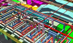
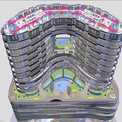
- The information in design models, drawings and documents is collectively known as the ‘project information model’ (PIM). It is made up of a number of federated models which is created with the employer, architect, structural engineer, building services engineer, contractor, sub-contractors, suppliers etc. In this stage, the built asset might be represented by massing diagrams or 2D symbols representing generic elements, with some critical elements developed in more detail.
BIM Level 3: Developed design
Developed design (sometimes referred to as ‘detailed design’ or ‘definition’) develops the concept design into a dimensionally correct and co-ordinated design, with all the main components of the building and their suitability. It should provide sufficient information for applications for statutory approvals to be started.
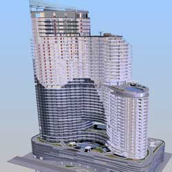
The supplier co-ordinates the development of the design based upon the approved concept design. The spatial coordination and information exchange processes described in PAS 1192-2 should be adopted to ensure the design team shares and coordinates information effectively. The supplier gives the project information model in accordance with the master information delivery plan. The project information model is developed based upon generic representations with approximate quantities, size, shape, location, tolerances etc
BIM Level 4: Technical design
The technical design stage (sometimes referred to as ‘design’) develops the design in sufficient detail for co-ordination to be completed and enables packaged, production information to be prepared which can be given to the contractor and their by to construct the development. Statutory approvals are to be completed. Technical design must be done by specialist subcontractors.
The supplier selects the specialist subcontractors to do the preparation of the technical design.
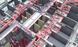
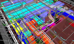
Model files with generic objects gets replaced with more specialist models containing specific objects with specifications and method statements attached, along with information about space allocation for operation, access, maintenance, installation, replacement and so on. Clash detection simulations should be done to demonstrate compliance with remaining building regulations and other statutory approvals, such as structural performance, energy use, acoustic performance, fire and smoke modelling and evacuation modeling.
BIM Level 5: Construction
Both on-site construction and off-site manufacturing is known as the construction stage (sometimes referred to as ‘build and commission
As project progresses BIM information becomes more detailed and it is expected to benefit industry.
Automated production of shop drawings, production of fabrication drawings is the main focus of BIM.
The BIM model might be linked to a project management scheduling tool. It may include; method statements, visualizations of potentially hazardous activities, delivery scheduling, formwork sequencing, traffic diversions and so on.
BIM Level 6: Handover and close out
The BIM model may be given to the employer, including the final published information and the archive which provides a record of all activities in the common data environment during the project.
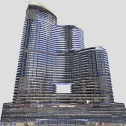
After the comparison of project information model against what has actually been constructed, it is handed over to the employer as an as-constructed asset information model (AIM). It is the model that compiles the data and information necessary to support asset management. It will have all the data and information related to, or required for the operation and maintenance of the building.
BIM Level 7: IN USE / asset information model (AIM)
‘In use’, sometimes referred to as ‘operation’, describes the period after any defects have been rectified and fine tuning carried out when the building is in ‘normal’ operation.
An asset information model (AIM) is developed from the as-constructed project information model (PIM), or the PIM is used to add an existing AIM. The asset information model compiles all the data and information related to, or required for the operation and maintenance of the completed building.
BIM LOD US and UK
| Common Data Environment | UK convention | US convention | Description |
| Design preparation and Brief Design | LOD 1 | Brief: a model communicating the performance requirements and site constraints. Building models would be block models only. | |
| Concept Design | LOD 2 | LOD 100 | Concept: a conceptual or massing model intended for whole building studies including basic areas & volumes, orientation, cost. |
| E.g. for an HVAC system, this might include block models of the plantroom locations and distribution risers. | |||
| Developed Design | LOD 3 | LOD 200 | A design development model, “generalized systems with approximate quantities, size, shape, location and orientation.” |
| E.g. for an HVAC system, this would be more what the architect above expected: duct runs modelled to approximate routes, but at an accurate overall size to include maximum potential sizes without detail of flanges or accurate radii of bends. | |||
| Technical Design | LOD 4 | LOD 300 | Production, or pre-construction, “design intent” model representing the end of the design stages. Modelled elements are accurate and coordinated, suitable for cost estimation and regulatory compliance checks. |
| This LOD would typically be a model suitable for production of traditional construction documents and shop drawings. | |||
| e.g. for an HVAC system, this is what the structural engineer was hoping for: accurate duct sizes & locations. | |||
| Construction | LOD 5 | LOD 400 | Installation: an accurate model of the construction requirements and specific building components, including specialist sub-contract geometry and data. |
| This model would be considered to be suitable for fabrication and assembly. Architects or engineers would rarely produce objects at this level. | |||
| e.g. for an HVAC system, the cut lengths of duct runs, fixings; a CAM model. | |||
| Hand over & close out | LOD 6 | LOD 500 | An “as built” model showing the project as it has been constructed. The model and associated data is suitable for maintenance and operations of the facility. |
| IN USE (AIM) | LOD 7 | Asset Information Model (AIM) used for ongoing operations, maintenance and performance monitoring |